Introduction
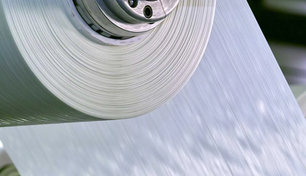
Continuous fiber reinforced thermoplastic (CFRTP) composites, produced in unidirectional tapes and laminate configurations, have the unique ability to add strength and stiffness while reducing manufacturing cycle times and enabling part consolidation of structural components in a wide variety of applications.
In this article, you will learn:
- What continuous fiber reinforced thermoplastic composites are, and how they differ from other composite materials
- Mechanical characteristics and advantages of CFRTPs
Comparing Composites
Design engineers know that when high strength-to-weight ratio is required, fiber reinforced polymer FRP) composites are the material of choice.
But choosing which composite material out of the spectrum of reinforcement and matrix combinations—from short to long to continuous fibers, and thermoset to thermoplastic resin formulations—is not so simple. Two characteristics often used to compare the attributes of FRP materials are performance and design flexibility. These factors can help determine which material best suits a particular application, based on processing and functional requirements.
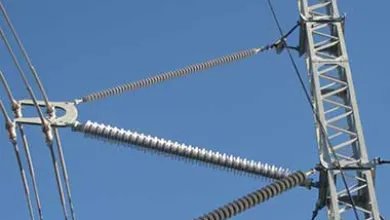
Continuous fiber reinforced thermoset composites combine high molecular weight resins with glass or carbon fibers. These products can operate at high temperatures and have strong mechanical properties. However, design flexibility is limited because, as thermosets, finished parts cannot be post-formed. Continuous fiber reinforced thermoset materials perform well in applications such as composite springs and archery bow limbs where consistent flexural performance is needed, and electrical transmission and distribution components where lightweight strength and weatherability are critical.

Long and short fiber reinforced thermoplastics provide outstanding design flexibility but offer varying performance ranges depending on their specific material composition. It is possible to create injection or compression molded plastic parts that would be difficult or impossible to machine using traditional materials such as steel or aluminum. These parts can be molded with assembly features in place to reduce product fabrication and secondary operations. Long and short fiber reinforced thermoplastics are well suited for applications requiring high strength-to-weight ratios as well as complex part geometries, such as automotive components and sporting goods.
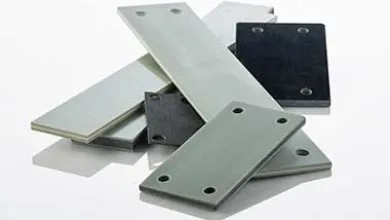
Continuous fiber reinforced thermoplastic composites offer a proportional balance of performance and design flexibility. The continuous fiber reinforcement provides strong and stiff material performance, while the thermoplastic resin matrix enables design flexibility through post-forming. These materials can be formed into multi-ply laminates to offer off-axis performance, post-molded into complex shapes, and overmolded with traditional thermoplastics to provide localized reinforcement in specific part locations. Various forming processes and application examples of CFRTP materials will be explored later in this article.
Want to learn more about the differences between thermosets and thermoplastics? Take a deeper dive into this article from the Idea Center.
CFRTP Structure and Performance
Continuous fiber reinforced thermoplastic composites are produced by pulling continuous glass rovings through thermoplastic resin to impregnate the fibers and form a unidirectional tape. This single-ply tape can be layered to form multi-axial laminate sheets and rolls by stacking layers of tape in varying directions and applying heat and pressure. The orientation, location, and volume of the fibers contribute to the strength and performance of the laminate structure.

Tensile Modulus
Tensile modulus measures the ratio of stress to strain along an axis and is one way to quantify the strength and stiffness of an FRP material. For example, when load or tension is placed on a composite longitudinally (in the direction of the fiber), the fiberglass reinforcement is resistant to the loading. The fibers will pull and eventually fracture but will withstand high loads due to the high tensile modulus of the reinforcement.
In contrast, when the loading is perpendicular (or transverse) to the fiber, the matrix of the composite is resisting the load. The resin has a lower tensile modulus than the reinforcement and will fracture at lower loads in this direction.
Increasing fibers in the direction of the load improves directional stiffness.

The graph above shows the result of tensile load applied longitudinally to three laminate samples made with Polystrand™ continuous glass fiber reinforced polypropylene in 2-, 4- and 6-ply configurations, illustrated below. The first two samples show similar tensile performance. This is due to the proportion of fibers in the load direction—in both cases, 50% of the layers are oriented in the longitudinal direction, resulting in similar tensile modulus. The third column has the highest tensile modulus.
The 6-ply laminate is developed for this load, with two-thirds of the layers oriented in the 0-degree direction. The greater ratio of fibers placed in the direction of the load increases the tensile modulus of the laminate.

The 4- and 6-ply samples in the above graph were loaded in the transverse direction. The 4-ply sample here has similar tensile performance as the 4-ply sample in Figure 1, which is expected because the two samples contain an equal balance of 0- and 90-degree fibers. The 6-ply sample has the lowest tensile modulus because the fiber loading in the transverse direction is much lower.
Flexural Modulus
The flexural modulus indicates a material’s resistance to bending. In the graph below, the 6-ply samples used flexural loads applied in both the longitudinal and transverse directions. The 6-ply sample has the highest flexural modulus when loaded in the longitudinal direction due to the higher ratio of 0-degree layers, as well as the location of the 0-degree fibers outside of the neutral axis. This same laminate configuration loaded in the transverse direction exhibits much lower flexural performance because there are fewer transversely oriented fibers to resist the bending load.
By combining unidirectional composite tapes into multi-axial, multi-layered laminates at specified fiber volumes, CFRTP materials can be developed to provide customized mechanical properties to meet specific performance targets.

Fiber Volume
Fiber volume is the ratio of fiber to resin in a composite structure. Increasing the fiber volume of a composite increases its mechanical performance, as illustrated in the graph below. In general, the more fiber used in the structure, the higher the performance. Polystrand thermoplastic composite materials can be produced with fiber volume percentages ranging from 58% to 80% to achieve specific performance requirements depending on the intended application. Fiber orientation, fiber location and fiber volume are three key variables in composite laminate design that affect the performance of the finished composite. By combining unidirectional composite tapes into multi-axial, multi-layered laminates at specified fiber volumes, CFRTP materials can be developed to provide customized mechanical properties to meet specific performance targets.
A 10% increase in fiber volume improved laminate stiffness by 25%.

Conclusion
Continuous fiber reinforced thermoplastic composites in unidirectional tape or multi-axial laminate form offer a balance of performance characteristics that are unmatched by other composite materials.
Looking for more? Explore Forming Methods and Applications for Continuous Fiber Thermoplastics to learn about the unique variety of processing methods that is possible with CFRTPs including:
- Secondary forming and methods for manufacturing complex geometries
- Various applications that benefit from the advantages of CFRTPs


